Just a quick update. I've purchased a Chuwi Hi10 Plus tablet from AliExpress to assist in PDF annotation and note taking for my Cisco studies. CCNA Security is next, and set for early next year. Look here for more updates. Click here for details on the Tablet, and I'l be sure to update you all when it arrives.
http://en.chuwi.com/product/items/Chuwi-Hi10-Plus.html
UPDATE:
Literally 3 months later, and from a different reseller the tablet finally showed up. It's slow, expected from an Atom processor. It works great at client sites while testing wired or wireless connectivity. Or to console into a Cisco device so i don't have to drag my larger laptop around.
Friday, December 15, 2017
Sunday, December 3, 2017
CCNA Success and more!
In November of 2017, I've passed the CCNA by passing both Cisco ICND1 and ICND2 exam requirements. This goal has been long over due, and I thank all whom assisted in me obtaining the certification.
I've also started back onto the NodeMCU unit, I see that I've been lacking since January. I havn't done much, since selling our house the garage door project has been axed. I've since gotten other electronics and gadgets like relays and distance sensors. I'm wanting to control all lighting in the house through my NodeMCU or Arduino. More to come, as well as Cisco :)
I've also started back onto the NodeMCU unit, I see that I've been lacking since January. I havn't done much, since selling our house the garage door project has been axed. I've since gotten other electronics and gadgets like relays and distance sensors. I'm wanting to control all lighting in the house through my NodeMCU or Arduino. More to come, as well as Cisco :)
Saturday, February 18, 2017
Re-purpose Barracuda WebFilter 310 with PFSense
Hello all,
while waiting for the correct power distribution for my NodeMCU project. I obtained two Barracuda WebFilter 310s, one from the 2010 and another from the 2013 area. At first, I simply put Ubuntu 16.10 on it, however I want to reduce power consumption on my current OPNSense server I'm running, as well as remove a PowerEdge server which is simply running a Python script for a client.
Ultimately, here's the steps I took to get this setup working. The CPU heatsink fan is literally a turbine, and way too loud. I've temporally placed a Zalman Heatsink/Fan, The Ubuntu installation went fine since I only required 1 NIC. however this wasn't the case for PFSense.
The front two NIC are activated by several relays on a breakout board. Which are actually fed from the Parallel port on the motherboard, which kinda makes it easy for us to mess with.
- While the Barracuda WebFilter boots, the relay kick on the NICs for Network boot, or whatever the Barracuda propitiatory does
- Once PFSense starts booting (which needed to be installed by a CD) the relays tick off causing the front NICs to stop operating
- I found that if you disconnect power to the relay breakout board and reconnect the Ethernet works for about 5 seconds. Meaning something in the software's not fully activating the relay
- In researching, I'm finding that you're able to edit the parallel port through C
I'll let this link explain the specifics: https://forum.pfsense.org/index.php?topic=85012.0. Partially down the page, you're given a list of instructions to find out if you're able to read the Parallel pin definitions.
The CPU installed in my particular unit was an Intel Celeron G540 so 64 bit. While attempting to issue the commands listed in the threat post. I ran into an issue with missing libraries in my PFSense install:
Download the required files:
fetch -o /tmp https://sites.google.com/site/pfsensefirebox/home/readio
/tmp/readio
fetch -o /tmp https://sites.google.com/site/pfsensefirebox/home/writeio
/tmp/writeio
Change permissions to execute files:
cd /tmp
chmod 0755 readio
chmod 0755 writeio
Execute Read file to see if Parallel port is able to be read:
./readio 0x378
Received this error:
ELF interpreter /libexec/ld-elf.so.1 not found
Aborted
I've corrected this by issuing the following commands:
fetch ftp://ftp.freebsd.org/pub/FreeBSD/releases/amd64/10.1-RELEASE/lib32.txz
tar -xvpJf lib32.txz -C /
Then, after issuing this final command I was able to utilize the Front NICs
./writeio 0x378 0x08
UPDATE:
While placing the Barracuda into production, i found that the Parallel settings didn't keep after shutting down the firewall. I needed to perform the following:

UPDATE:
While placing the Barracuda into production, i found that the Parallel settings didn't keep after shutting down the firewall. I needed to perform the following:
- Move the readio and writeio to a static folder, in my case I did /frontnics/
- In PFSense go to Diagnostics -> Edit File
- The file we're editing is: /conf/config.xml
- Place this just above the </system> string: <shellcmd>/frontnic/writeio 0x378 0x08</shellcmd>

Now when you reboot or shudown the firewall, the front ports will be active.
Thank you
Thursday, January 19, 2017
NodeMCU has Arrived!
It's Here!
I'm currently on the business trip and while at the hotel, I decided to experiment.


Below is the top schematic view of the NodeMCU, credit goes to this website for the image and python code used.
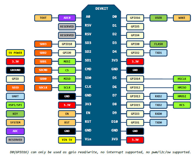
Essentially, I created a short video displaying a python script, which was taken from the link above(with some modifications). Once I have the remaining project items, I'll be continuing the Garage Door Project. Till then, I'll keep on experiencing. Enjoy:
Saturday, January 14, 2017
Electronic Components 101
The basics of electronic components/theory is where I'll begin this post. Several websites explain in great detail. However, I learn at a visual and 'example' level, if there's no scenario of the device or example in production i really do no grasp it. So, this may seem overboard however it's the way I learn.
We have two standards of Electronic Signal:
We have two standards of Electronic Signal:
- AC (Alternating Current):
- Current is constantly reversing, Telsa's answer to Edison's Direct Current limitation. The Rate of Reversal is measured in Hertz
- DC (Direct Current):
- Flows in one direction between Power and ground. There's always a positive source of voltage and ground.
Electricity is typically defined as having a voltage and current rating(AMP). Electricity can also be defined in resistant and watts. Never exceed the Wattage rating of a component, you can Calculate the wattage, by V * I(AMP). For Example:
A Laptop Power supply which supplies 20Vs at 3.25Amps. Equals power delivery of 65Watts.
20 * 3.25 = 65
Circuits:
Closed Circuit - Allow the flow of electricity between power and ground
Open Circuit - Would break the flow of electricity between power and ground
Resistance:
Electricity in a circuit must be used. Also, electronic devices need some type of resistance in their circuity. If not, those electronic devices will short circuit, or burn. It's very important to know that Positive is never directly connected to ground. Also remember that a switch will not add resistance to a circuit. If you were to connect a switch between + and -, the circuit will short.
Series VS. Parallel:
Series - circuits are wired one after another, such that electricity has to pass through one component to the next.
Parallel - Wired side-by-side, such that electricity passes through all components at the same time.
Tuesday, January 10, 2017
A 2-Channel Relay
Good evening everyone,
If you're using a electrical outlet for example, you'd splice the positive the wire to COM and another to NO or NC. Then depending on the configuration of the relay, you would do directly to AC current or be controlled through a Microprocessor.
On the back are the connections to either the micro controller or to AC:
The reason I'd be using a 2-Channel Relay, in the event of a power failure a reboot of the micro controller would typically cause the circuit to activate upon restart. By placing a jumper wire between the two common pins, this operation is prevented.
Full Disclaimer, this is my first time really delving into electronics. If you find any of my data incorrect, please inform me. I want my audience and myself educated the correct way.
Further details can be obtained from Wiki or from this Source and this great source.
I thought it would be neat to do some investigation and research on how each part operates as it arrives in the mail. So the first item is this 2-channel 5V DC relay. You would typically use these units to power higher voltage circuits with a lower voltage. In the project, this relay will be used to open and close my garage through a NodeMCU controller.
Relays have a built-in switch essentially, when a voltage change the electromagnet is charged or not, thus causing the common terminal armature to move between NO or NC.

Relays have a built-in switch essentially, when a voltage change the electromagnet is charged or not, thus causing the common terminal armature to move between NO or NC.

The Front section of the Relay focuses on connectivity to the External device.
NC1(Normally Connected Channel 1) COM (Common Pin) NO1(Normally Open Channel 1)
|
 |
If you're using a electrical outlet for example, you'd splice the positive the wire to COM and another to NO or NC. Then depending on the configuration of the relay, you would do directly to AC current or be controlled through a Microprocessor.
On the back are the connections to either the micro controller or to AC:
Right:
Left:
|
 |
The reason I'd be using a 2-Channel Relay, in the event of a power failure a reboot of the micro controller would typically cause the circuit to activate upon restart. By placing a jumper wire between the two common pins, this operation is prevented.
Full Disclaimer, this is my first time really delving into electronics. If you find any of my data incorrect, please inform me. I want my audience and myself educated the correct way.
Further details can be obtained from Wiki or from this Source and this great source.
Sunday, January 8, 2017
Use IoT NodeMCU to open Garage Door

Based on the Makezine article listed here, but same approach with a NodeMCU IoT device.
I'll start with saying I've always had a fascination with Electronics, but I've traveled down the IT path. Today, I'm beginning a new venture, into home automation. Sure multiple example exist about using a smart phone to automate your life. I'm trying to force myself to learn electronics while doing this project, and many more.
First, I've already ordered my equipment:
- 2 Channel DC 5V Relay Switch
- NodeMCU Wireless ESP8266 Module with CP2102 USb Interface
- Adafruit DHT11 Temp & Humidity Sensor
Second, I ensured my Arduino application included the NodeMCU/ESP8266 board, I've used the following link. I'm using Linux Mint 18.1, so Mine looks like the following (Parsed to remove personal data):

Third, research. As stated, I'm aiming to gain electronics experience during this process.
Thanks.
Subscribe to:
Posts (Atom)